What Is Infill in 3D Printing? 7 Patterns Compared for Toys
Infill is the internal pattern printed between a model's outer walls. It supports top surfaces and influences material use, print time, weight, and stiffness, but it does not determine toy durability by itself.
For a decorative shell, a validated low-density profile may be enough. Wheels, clips, hinges, handles, and other loaded features need a full-scale test because walls, geometry, orientation, layer bonding, material, and the direction of force can matter more than one percentage.
More infill is not automatically better. Start from the printer's tested profile, inspect the layer preview, compare time and grams, and change one variable only when the model has a defined structural or top-surface need.
This guide explains what the percentage controls, compares seven common patterns, and shows how to choose a testable starting point without turning a slicer heuristic into a universal toy-safety rule.
Quick Pick: Where to Start
Skip ahead if you only need a number. Detail follows.
|
Toy Type |
Start At |
Pattern to Try |
Reason |
|
Miniature or shelf figure |
10% |
Lines or lightning |
A low-load display piece may need only enough internal support for its top surfaces |
|
Everyday toy body |
20% |
Grid |
Familiar balance of speed and support |
|
Toy car body |
20% |
Grid or cubic |
The shell may provide much of the structure; test wheels, axles, and clips separately |
|
Wheels, hubs, axle parts |
30 to 40% |
Cubic |
Force arrives from several directions |
|
Building bricks and connectors |
30 to 40% |
Gyroid or cubic |
Repeated pushing and pulling |
|
Flexible or bendable part |
15 to 20% |
Concentric |
Internal paths follow the outer shape |
|
Large prop, helmet, costume piece |
5 to 10% |
Lightning |
Filament cost climbs fast on big volumes |
|
Small functional insert |
60 to 100% |
Any dense setting |
Use only when a tested functional requirement justifies a dense interior |
What Infill Actually Is

Infill sits between the outer walls of a print. It repeats as a geometric shape: straight lines, a crossing grid, hexagons, stacked cubes, or smooth waves. Nothing exotic.
Infill supports top surfaces and can help the walls resist compression. It also keeps a part from becoming a solid mass of plastic, which can reduce material use and print time compared with a dense interior.
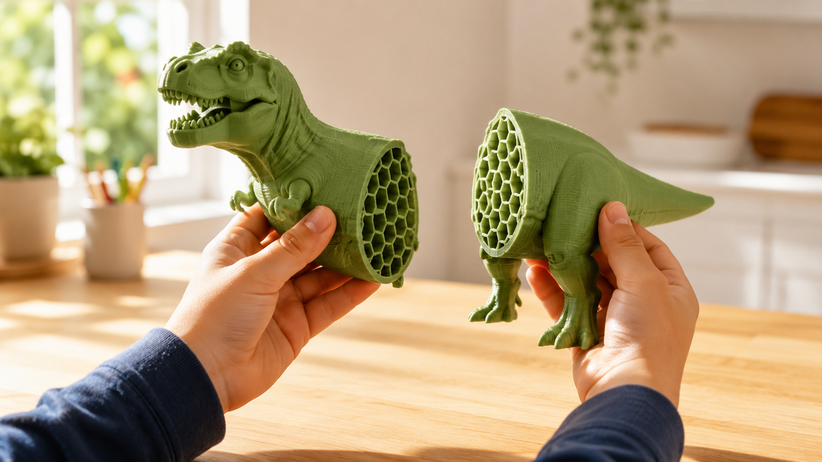
Cut a printed toy in half and the whole pattern is right there.
How the slicer builds it
The printer decides none of this. Your slicer generates the internal paths before printing starts, using the density and the pattern you selected. Software decides.
During the print, the nozzle traces the walls for a layer, then fills in the internal lines for that same layer. Top layers close over the pattern and hide it for good. Gone from view.
Infill percentage is a slicer setting that controls the spacing or target density of internal paths; it is not the percentage of the entire finished object that is plastic. Implementations vary, so compare the layer preview and estimated grams in the exact slicer/profile.
Infill, walls, and top layers
Three settings share the work. Walls form the visible outside. Top and bottom layers close the model. Infill supports both from inside. Three jobs, one part.
Walls take the first hit in a drop or a squeeze, because that is where the force enters the part. Infill backs them up from behind. Second line of defence.
So raising infill is not automatically the answer to a weak toy. Sometimes one more wall does more work, for less plastic and less time.
|
Before you change anythingSlice the toy once at the current settings and record the estimated time and filament weight. Use that baseline to compare one controlled change at a time. |
What the Infill Percentage Really Means

Density controls how tightly the pattern packs together. Low leaves large open pockets. High squeezes the lines close. Simple slider.
More density normally brings more filament, weight, time, and rigidity, but the size of the gain depends on the model, walls, material, pattern, and load. Compare the next setting in the slicer and test the critical feature rather than assuming the gain stays constant.
Treat the percentage as a starting range rather than a universal rule.
|
Setting |
What You Get |
Good For |
The Trade |
|
0% |
Hollow between walls and top layers |
Vase style models, thin decorative shells, some props |
Wide flat roofs inside the model may sag with nothing under them |
|
10% |
Sparse internal framework |
Display figures, prototypes, low stress toys |
Thin legs and narrow connectors stay fragile |
|
20% |
Light but continuous support |
General toy bodies, vehicles, puzzle pieces |
Still depends on wall count and orientation |
|
30 to 40% |
Denser framework |
Wheels, handles, connectors, thicker moving parts |
Noticeably heavier and slower on large models |
|
50 to 75% |
Dense interior |
Parts where internal rigidity is the point |
Wasteful for a body with thick walls and light use |
|
100% |
Nearly solid |
Small functional pieces only |
Longest print, most filament, rarely worth it for a toy |
What the test data actually shows
Published infill studies show that measured strength can change with density, pattern, specimen geometry, material, print settings, and loading method. In the cited test, grid produced the lowest result among the patterns tested under those specific conditions, but that does not make grid the weakest choice for every geometry or load case. Treat the result as one data point and test the finished part in the direction and type of force it will actually experience.
Higher infill often increases stiffness or strength in a given test, but the size and shape of the gain depend on material, pattern, geometry, processing, and load case. Use PLA-specific evidence for PLA advice and validate the finished toy rather than assuming a universal plateau..
Two points follow from those tests: density can help within the tested setup, and the benefit is not necessarily linear. Apply the trend cautiously because the useful range changes with geometry, material, orientation, and failure mode.
Those specimens were flat test bars, not your dinosaur. Use the trend, not the exact figures.
|
100% is not a repair. A part can still crack at 100% infill if it broke along a layer line, if the wall was too thin around a hole, or if a connector neck was narrow by design. Solid plastic does not fix geometry. Find where it failed first. |
7 Infill Patterns Compared for 3D Printed Toys

Two toys printed at the same percentage can behave differently when the pattern changes. Some patterns run fast and straight. Others build a genuine three dimensional structure that resists force from several angles. Big difference.
These seven cover many patterns a family is likely to see in a slicer. Availability and implementation vary by software, so compare the actual preview and estimate for the selected printer profile.
|
Pattern |
Internal Shape |
Common Toy Use |
Speed |
Watch For |
|
Lines |
Straight paths, direction alternates by layer |
Prototypes, display figures |
Often fast |
Little support across other directions |
|
Grid |
Crossing lines forming a flat lattice |
Everyday bodies, vehicles |
Profile-dependent |
Results vary by load, density, and test method |
|
Honeycomb |
Repeating hexagonal cells |
Toy bodies, cases, shells |
Profile-dependent |
More nozzle travel than lines |
|
Cubic |
Stacked and tilted cubes in 3D |
Wheels, brackets, connectors |
Profile-dependent |
Longer paths than a flat grid |
|
Gyroid |
Smooth continuous waves in 3D |
Twisted or pressed parts, flexibles |
Often more toolpath complexity; verify in the slicer |
Complex toolpath, adds time |
|
Concentric |
Rings following the outer wall |
Bendable shells, soft parts |
Profile-dependent |
Poor multidirectional stiffness |
|
Lightning |
Branching supports near the top only |
Large props, decorative pieces |
Often fast |
Designed mainly to support upper surfaces, not to fill the whole interior |
1. Lines: fast and simple
Lines runs straight paths inside the model and flips direction each layer, so the structure does not stay aligned one way through the whole part. Alternating helps.
Lines often create simple toolpaths, but time and material use vary by slicer and model. Compare the predicted grams and time against grid, cubic, and gyroid in the same profile before choosing.
Because the load response is directional, avoid choosing lines by speed alone for parts that will be pushed or twisted. Test the loaded feature or compare a multidirectional pattern.
2. Grid: a common general-purpose pattern
Grid crosses lines to form a flat lattice that is easy to inspect in the preview. It is a common general-purpose option, but its performance still depends on density, line width, walls, material, orientation, and load direction.
For general toy work, grid can provide a practical balance of internal support and uncomplicated toolpaths. Treat it as a starting option rather than a default that is strongest or fastest for every model.
In one cited tensile study, grid ranked lowest among the specimens and conditions tested. That result does not establish a universal ranking for every material, model geometry, density, slicer implementation, or load case.
3. Honeycomb: strong for the weight
Honeycomb builds repeated hexagonal cells. The geometry spreads load evenly while leaving real space between the printed lines. Efficient shape.
Honeycomb can be worth comparing when a toy body needs internal support at moderate weight. Its actual stiffness, print time, and failure behavior depend on density, wall design, material, specimen geometry, and load direction, so verify the sliced estimate and test the loaded feature.
Cost is toolpath complexity. Expect more time than lines at the same density.
4. Cubic: support in three directions
Cubic stacks and tilts cubes so the structure varies through the height of the model rather than repeating identically on every layer. Depth, not layers.
That makes it a strong candidate for functional toy parts. Wheels, handles, brackets, and construction pieces all take force from angles nobody planned for. Kids find them.
Compare it against gyroid in your slicer before committing to a long print.
5. Gyroid: smooth curves, even support
Gyroid uses flowing curves that connect continuously through the model. No sharp internal intersections, no stacked flat lines. It flows.
Gyroid creates a connected three-dimensional path that can be useful when a part is loaded from several directions. It is not automatically the strongest or fastest option; compare it with cubic or rectilinear infill using the same model, density, walls, material, and profile.
It is rarely the fastest option. That is the trade.
6. Concentric: follows the shape
Concentric traces the outline of the model and repeats inward, instead of filling the interior with a crossing grid. Rings inward.
Useful when a part should flex with its own outer form. Soft shells, bendable components, and parts designed to absorb a squeeze all suit it. Bend, not break.
Concentric may provide less multidirectional stiffness than cubic or gyroid in a rigid part, but the result depends on density, shell design, material, and how the part is loaded.
7. Lightning: least plastic inside
Lightning branches upward like a tree and places material only where the upper surfaces need something underneath. Large sections of the interior stay nearly empty. Very little plastic.
Lightning can reduce internal material in large decorative shells because it mainly supports upper surfaces. Check the exact slicer estimate against a low-density grid or gyroid profile; do not use it as a durability strategy for parts that will be struck, bent, or load-bearing.
Lightning is intended mainly to support upper surfaces rather than create a uniformly load-bearing interior. Use another structure, stronger geometry, or a local test when the part must carry force.
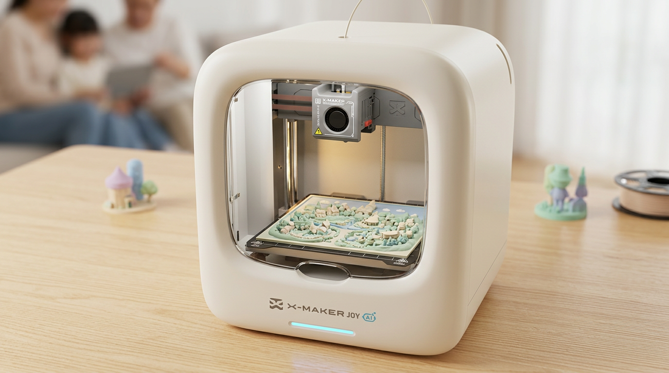
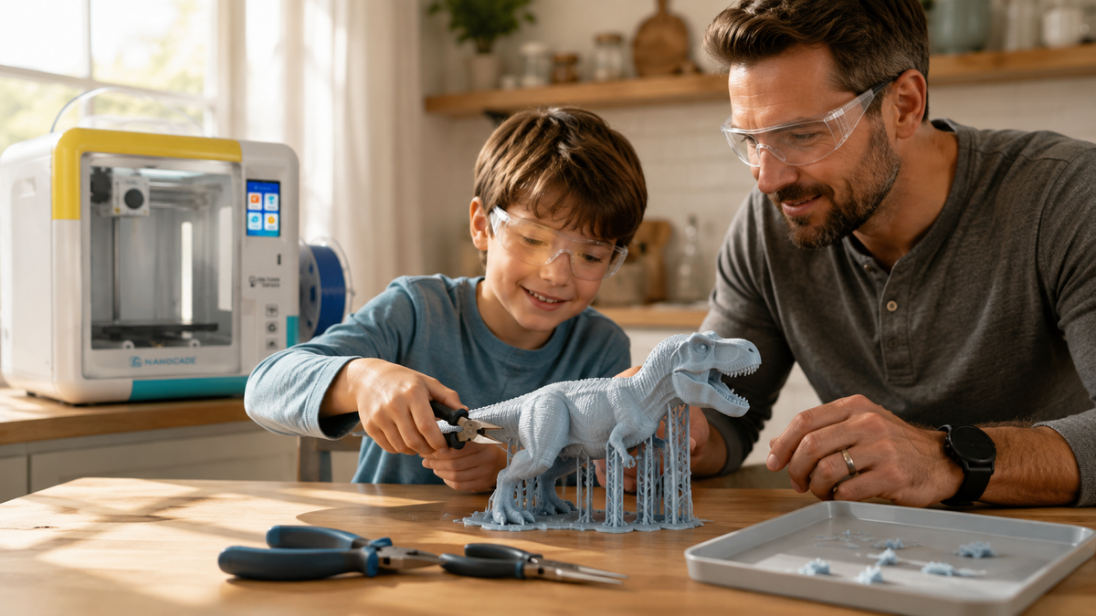
AOSEED’s guided app can reduce the number of settings a child sees, while a responsible adult follows the current manual for setup, approved materials, supervision, ventilation and exposure controls, print monitoring, troubleshooting, and part removal.
Which Toys Need Which Interior
Start with what the toy does after it comes off the plate. Then pick the interior that matches.
Miniatures and display figures
These only need to hold their shape and look right on a shelf. Lines, a light grid, or lightning all work depending on size. Low stakes.
Very small figurines contain so little interior that wall settings matter more than density. Check the sliced preview rather than assuming every miniature wants the same value.
Action figures and character toys
Handled far more than display pieces, especially with moving arms, legs, or clip on accessories. A moderate interior makes the main body feel solid in a hand.
Grid, cubic, and gyroid are all reasonable. Small joints usually fail before the torso does, so treat those as a geometry problem, not a density problem. Fix the joint.
Articulated and print in place toys
Performance here depends on clean gaps and joints that do not fuse. Dimensional accuracy, wall placement, orientation, and material behavior may matter more than raising infill, so inspect the joint in the sliced preview.
Grid, cubic, or gyroid can support thicker body sections at lower percentages. What matters is that generated infill stays inside the walls and does not intrude into a designed clearance. Check the layer preview before printing.
Toy cars and wheels
Car bodies often work at a moderate density because the shell provides much of the structure. Around 20% can be a useful starting point, but wheels, axles, and clips should be tested separately.
Do not assign wheels, axles, or clips a universal density. Print the critical feature at full scale with the validated profile, test it in the expected direction of force, inspect where it bends or breaks, and then change geometry, walls, orientation, or infill one variable at a time.
Test one wheel. Then print four.
Building sets and connectors
Connectors get pushed, pulled, twisted, and forced together by children who do not read instructions. Fit tolerance matters as much as strength, because a connection that is slightly too tight puts constant stress on the wall. Tight is risky.
Cubic, gyroid, or a denser grid all hold up. Watch wall thickness around the connection point. A dense core cannot save a wall that is one line thick where the stud meets the socket.
Fidget toys
These rotate, slide, click, or bend, so the right interior depends on whether the part should feel rigid or springy. Depends on the part.
Gyroid suits parts under force from several angles. Concentric works better when a flexible section should follow its own outer shape. Print in place fidgets live and die on clearances, so calibrate before you chase density.
Large props and pretend play pieces
Helmets, oversized tools, and costume parts eat filament if you fill them. They mostly need shape, not a solid core. Shape sells it.
Lightning, lines, or a low grid keep the weight down. If one handle or joint has to carry load, reinforce that section on its own instead of making the whole prop dense. Splitting a big model into sections also makes reprints cheaper when something goes wrong.
What Density Costs in Time, Weight, and Filament
Every internal line adds filament and nozzle movement. Raise density or choose a more complex pattern only after comparing the added time and material in the slicer estimate.
Why density adds hours
A denser setting creates more internal paths, and the nozzle must travel them across many layers. On a large interior volume, the added duration can be substantial; use the slicer estimate for the actual model rather than a generic hours-versus-minutes rule.
A small figure may barely notice. A helmet will. Read the slicer estimate before you commit to the bigger number.
Walls often beat density
One cited PLA study found similar reported results for two specific hexagonal specimens that used different infill density and line-width combinations. The result belongs to that specimen, material, print setup, and test method; it does not show that doubled line width generally replaces higher infill in a toy.
The practical version for toys is to inspect the failure location before changing density. If the shell or a narrow neck fails first, test an additional wall or a geometry change; if a broad top surface lacks support, compare a modest infill change.
Heavier is not better
More plastic inside means a heavier finished toy. That is not automatically an upgrade.
A light prop is easier for a child to hold up during play. A light articulated figure puts less strain on its own joints. Some functional parts do want mass, and those are worth the filament. Match the weight to the purpose. Nothing more.
How to Set Infill for a Family Print
Most slicers keep these controls together under strength, structure, or print settings. Names vary. The controls do not.
- Pick the density from the job, using the quick pick table above as a starting point.
- Pick the pattern from the direction the force will come from.
- Slice it, then scroll the preview layer by layer instead of looking only at the outside.
- Look for wide flat roofs sitting over sparse infill. That is where sagging starts.
- Note the time and filament estimate, change one setting, and reslice to compare.
- Print one important section first. A wheel, a joint, a connector. Test it by hand before you print the set.
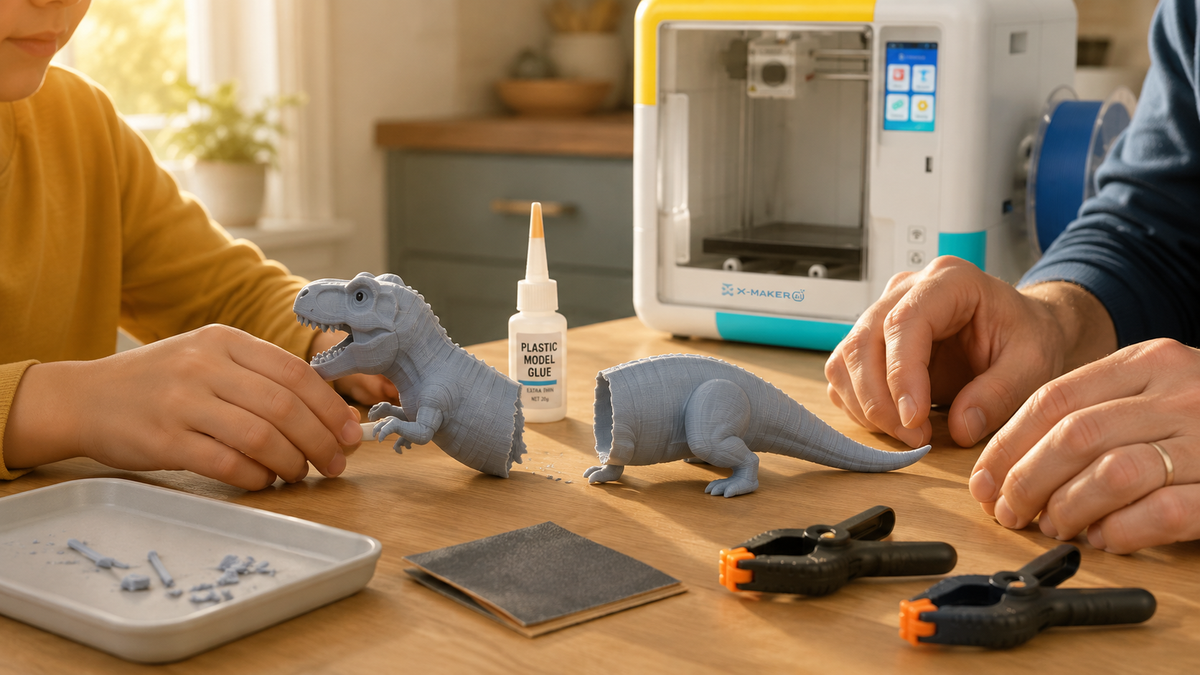
In a guided workflow, children can browse or customise a model while an adult reviews infill, walls, orientation, and print time. The useful buying criterion is whether the app exposes enough information for supervision without making the child manage every advanced setting.
|
Setup noteA printer is equipment, not a bedroom toy. Follow the product manual and applicable safety guidance for placement, ventilation, material, enclosure use, temperature, cleaning, and supervision. The NIOSH guide to safe 3D printing and university EHS guidance provide useful control questions for shared rooms. |
Common Infill Problems in Printed Toys

Not every failure is a density failure. Look at where the problem shows up before you touch the slider. Location tells you plenty.
|
What You See |
Likely Cause |
Check This First |
|
Gap between the infill and the wall |
Too little infill to wall overlap, or inconsistent flow |
Nudge the overlap slightly, print a small test, do not make a big jump |
|
Thin or missing internal lines |
Under extrusion, speed too high, partly clogged nozzle |
Look at the preview. If the gap is already there, it is a settings issue, not the printer |
|
Sagging or rough top surface |
Wide roof over sparse infill |
Raise density slightly or add a top layer, rather than filling the whole model |
|
Print takes far longer than expected |
High density on a large interior volume |
Compare estimates at 20% and 30%. Also check the pattern |
|
Warping on a big part |
Cooling stress, bed adhesion, dense interior contributing |
Retest at lower density and change one variable at a time |
|
Flexible part feels stiff |
Rigid pattern or too much material inside |
Try concentric or gyroid, and drop the density |
|
Connector snapped at the neck |
Geometry and wall thickness, not the core |
Add a wall, thicken the neck, or reorient the part |
When to Raise Infill, and When to Leave It Alone

Raise it when:
- The part carries load in normal play, like a wheel hub, a handle, or a connector.
- A wide top surface sags in the preview with nothing supporting it.
- The finished piece flexes more than the design intends when you press it.
- You need mass in a small functional insert for it to work properly.
Leave it alone when:
- The toy sits on a shelf, hangs on a wall, or gets handled gently.
- The break ran along a layer line, which points at orientation and layer bonding.
- The crack started at a hole, a corner, or a thin edge, which points at walls and geometry.
- The model is large and the slicer shows filament use climbing sharply for a small strength gain.
Conclusion
Infill gives a printed toy an internal structure without making the whole object solid. Choose density from the expected use, choose a pattern from the load direction and geometry, then compare the slicer preview, time, and filament estimate before testing the critical part.
For a non-load-bearing toy shell, 10–20% can be a slicer starting point. Do not use a universal percentage for wheels, connectors, handles, or other loaded parts; review walls and orientation, compare profiles, print one sample, and test it under the intended use before making the set.
Print one test part. Then print the set.
If you are choosing hardware, compare build volume, supported materials, enclosure design, preview access, and the amount of the workflow an adult can review. Before buying, verify the exact model’s current specifications, age and supervision guidance, ventilation and operating requirements, price, warranty, and return terms on the manufacturer’s regional product page and manual.
FAQs
What infill percentage should I use for a 3D-printed toy?
For a decorative or lightly handled toy, 10% to 20% is a practical starting range. Parts that are squeezed, twisted, or repeatedly loaded may need more infill, more walls, or a geometry change, so test the critical part before printing a full set.
Does more infill always make a toy stronger?
No. Infill can improve stiffness and compression resistance, but it cannot compensate for a thin joint, poor layer bonding, or an orientation that puts the load across weak layer interfaces.
- If the shell cracks first, add a perimeter or strengthen the geometry.
- If a broad top surface sags, increase support below it or adjust infill.
- If a clip splits along layer lines, change orientation before raising density.
Which infill pattern works well for moving toys?
Choose the pattern by how the part is loaded, not by a universal ranking.
- Cubic or gyroid: useful starting points for parts loaded from several directions.
- Rectilinear or grid: straightforward choices for prototypes and general bodies.
- Concentric: useful when controlled flex follows the outer shape.
- Lightning or support-focused patterns: better suited to large decorative shells than load-bearing joints.
How do I choose between more infill and more walls?
Look at where the part fails, then change one setting at a time.
- Inspect the crack, bend, or sagging area.
- Add a wall when the outer shell or a thin neck is failing.
- Raise infill when internal support or compression resistance is the limiting factor.
- Reslice and compare print time, filament use, and the layer preview.
Can 0% infill work for a toy?
Yes, if the model has enough walls and its upper surfaces close gradually without long unsupported spans. If the toy will be squeezed, dropped, or has a wide flat roof, use sparse infill or print a small test section first.
Is 100% infill necessary for kids' projects?
Rarely. Use 100% only when a specific engineering need justifies a nearly solid part; for most toys it adds time and material without fixing weak geometry, poor orientation, or inadequate walls.
Sources
- Polymers, “Effects of Infill Line Multiplier and Patterns on Mechanical Properties of Lightweight and Resilient Hollow Section Products Manufactured Using Fused Filament Fabrication”
- Journal of Composites Science, “Effects of Infill Density and Pattern on the Tensile Mechanical Behavior of 3D-Printed Glycolyzed Polyethylene Terephthalate Reinforced with Carbon-Fiber Composites by the FDM Process”
- National Library of Medicine, PubMed Central, “On the Behavior of Honeycomb, Grid and Triangular PLA Structures under Symmetric and Asymmetric Bending”
- National Institute for Occupational Safety and Health, “Approaches to Safe 3D Printing: A Guide for Makerspace Users, Schools, Libraries, and Small Businesses”
- Princeton University Environmental Health and Safety, “3D Printers on Campus”


Further reading

STEM Building Toys for Kids: Blocks, Kits and Printers Compared

Toy 3D Printer: What to Look for in a Printer That Makes Toys at Home

Personalized Gifts for Kids: Name Tags, Keepsakes and Custom Toys You Can Design