How to Orient a 3D Model for Printing: 10 Beginner Rules
The best 3D-print orientation balances five checks: stable bed contact, expected load direction, support use, visible-surface quality, and fit inside the build volume. No single position wins for every model.
Start with a broad stable face, then inspect the trade-offs in the slicer. A flatter position may reduce height or support, but a large flat footprint can still warp, hide important detail, weaken a loaded feature, or exceed the available plate area.
Use the 10 rules below as a decision sequence, not absolute laws. Preview the complete toolpath and print the risky feature at full scale when strength, fit, overhangs, or support removal matter.
Quick pick: choose a starting orientation
|
What you are printing |
Start with |
Why |
|
Flat toy, keychain, or nameplate |
A broad stable face on the plate |
Usually improves bed contact and can reduce support |
|
Tall figure or tower |
Upright only when the base is stable; otherwise test a tilt or split |
Reduces tipping risk without assuming one angle works for every model |
|
Long arm, wing, or ledge |
Rotate while watching the support preview |
The useful position depends on slope, cooling, speed, and surface priority |
|
Part that will be pulled or bent |
Align the load with continuous extrusion paths where practical |
Reduces the chance that the load peels layer interfaces apart |
|
Bowl, cup, or hollow shell |
Keep cavities open or split at a logical seam |
Avoids trapped support and improves access for inspection |
|
Model near the printer's size limit |
Measure, preview, then scale or split |
Confirms the complete model, brim, and travel fit the documented build area |
Why orientation decides whether a print succeeds

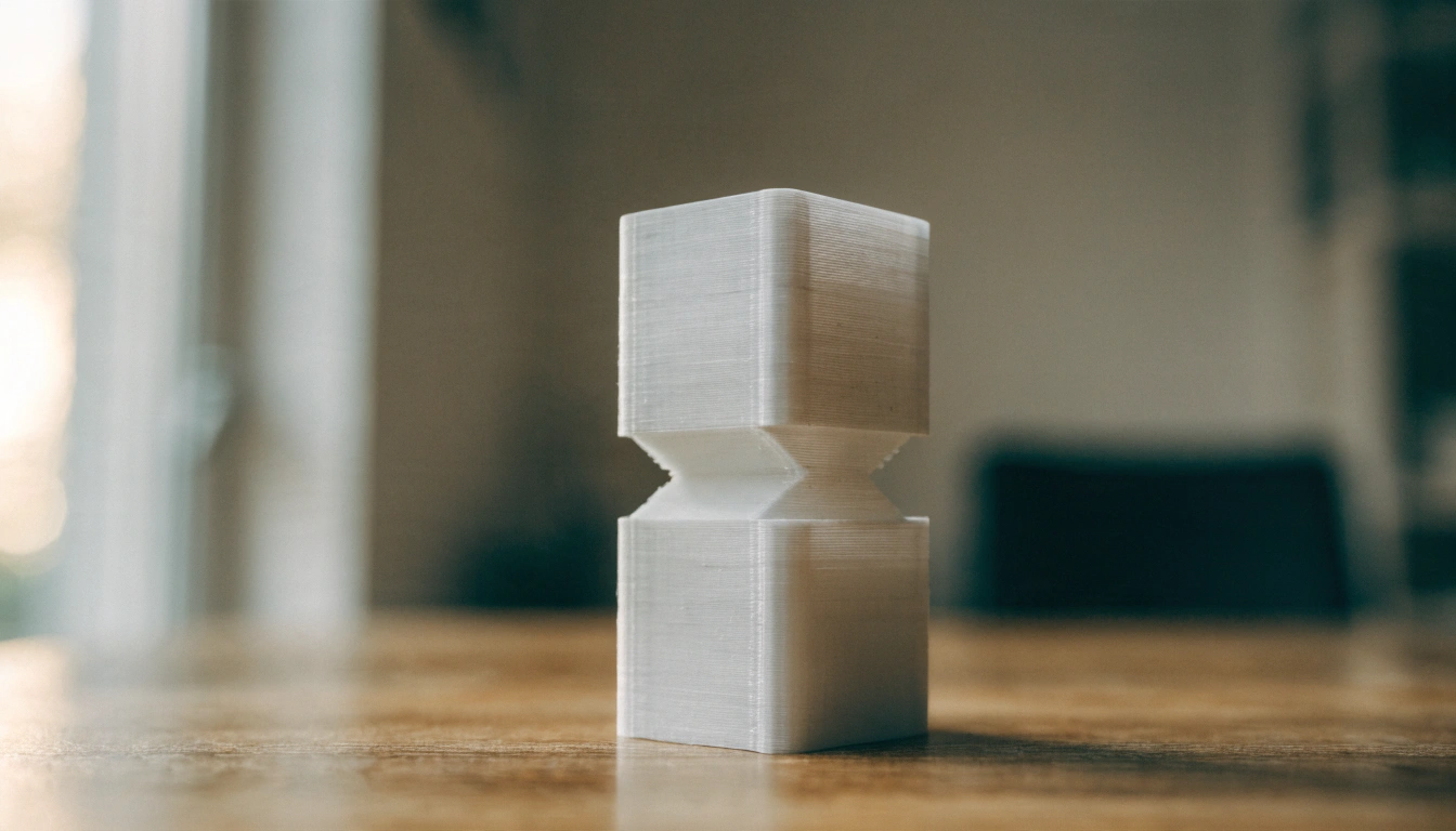
An FDM printer builds one layer over another, so the finished part can behave differently by direction. Interlayer bonding may be weaker than continuous extrusion paths under some loads, but material, geometry, temperature, walls, orientation, and the test method all affect the result.
Many tensile studies report lower strength when the applied load tends to separate layer interfaces, but the result depends on the specimen and force direction. Orient critical features so expected loads are carried along continuous extrusion paths where practical, then test the finished part in its intended use.
A broader face can improve mechanical stability and reduce tipping, but it does not guarantee less warping. Large flat footprints can accumulate cooling stress and lift at edges, so compare contact area, thermal behavior, visible surfaces, and the validated profile.
|
Rule of thumbStart with a broad stable face and align continuous extrusion paths with the expected load where practical. Then confirm support, visible surfaces, dimensions, and build-volume fit in the slicer; no single orientation rule prevents every failure. |
The 10 beginner rules for orienting a 3D model
1. Put the largest flat face on the build plate

Start by placing a broad stable face on the build plate, then inspect the consequences. More contact may improve stability and reduce the need for a brim or raft, but another orientation may be better when it protects detail, improves load direction, reduces support scars, or fits the build volume.
2. Test a tilt before adding support
Unsupported plastic can sag, but there is no single overhang or bridge number that fits every printer, material, and profile. Rotate the model, inspect the slicer preview, and run a small test when the geometry is critical. A modest tilt can reduce support, while cooling, speed, layer height, and shape determine how far the printer can bridge or overhang reliably.
3. Orient loaded features to avoid peeling layers apart
For a printed hook or bracket, compare how the expected load crosses the layer interfaces. An upright position may expose a peeling failure, while a flatter position may align more continuous extrusion paths with the load. Confirm the result with the intended material, profile, and a representative load test.
4. Hide support scars where nobody looks
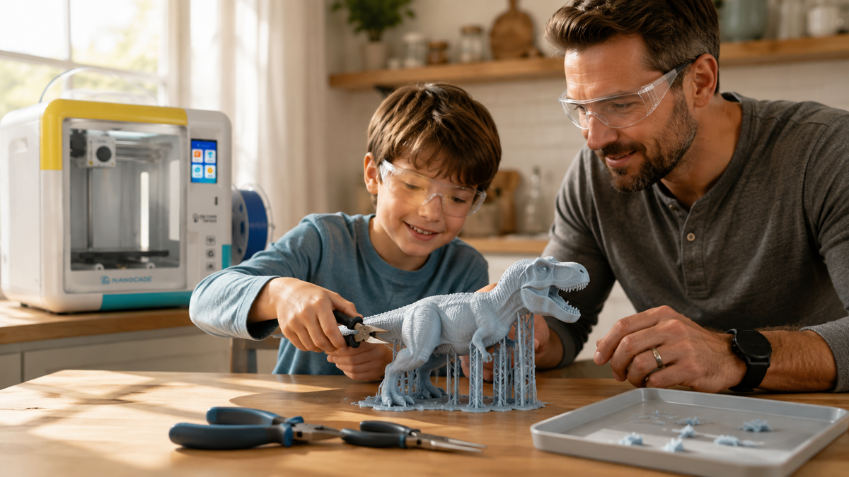
Support material can leave a rough contact surface after removal. Place support contact on the back, base, or a surface that will be joined when that choice does not create a worse strength, fit, or stability problem. For a figurine, test a small tilt in preview before assuming one angle will protect the face.
5. Confirm the model fits the build volume in that orientation
A 150 mm-tall figure does not fit upright in a 120 mm Z build height. It must be scaled, tilted if the full geometry remains within all printable bounds, or split into parts; confirm the complete sliced toolpath, not only the bounding box.
|
Safety note for home and classroom printingOrientation can change print duration and support removal. Follow the printer manual and applicable CDC/NIOSH and local guidance for enclosure use, placement, ventilation, material, operating temperature, cooling time, supervision, and opening the machine. Do not apply a universal wait time or material claim to every printer; verify the exact product and room setup. |
6. Keep cavity openings accessible and avoid unsupported ceilings
Cups, bowls, helmets, and open shells all cause the same trouble when the opening faces down. The roof of the cavity becomes a wide unsupported ceiling. Open side up. Flip it and that ceiling becomes a floor, printed straight onto the layer below. If flipping ruins the outside finish, split the shape at its widest point and print two halves face down.
7. Keep small pins and thin details off the top of a tall print
Thin, tall features are vulnerable when each layer is deposited before the previous one cools. Reliability depends on diameter, height, nozzle, material, and profile; print one representative feature or multiple copies spaced apart to test cooling before committing to the full model.
8. Split stubborn models into two halves
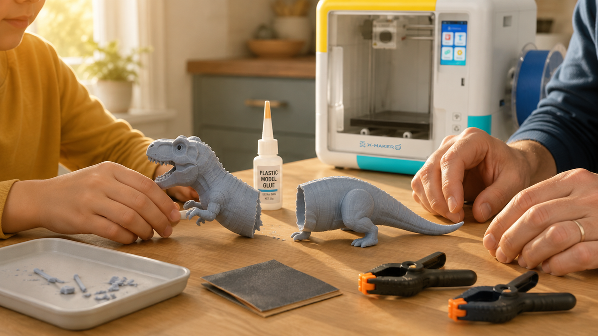
Some shapes have no clearly useful one-piece orientation. A sphere, for example, presents curved undersides in every position. Splitting the model at a logical seam may reduce support and improve access to the surfaces, but the result still depends on alignment features, adhesive, finishing, and the intended load.
9. Calibrate clearance for parts that must fit together
Do not assume a universal clearance. Print a small fit coupon with several gaps—for example, values around the designer’s starting estimate—using the exact material, orientation, and profile. Then select the fit that passes the intended assembly and use test.
10. Run a small test before committing to the full print
Test the risky feature at full scale: cut out the base, joint, overhang, or support-contact area and print that section with the final orientation and profile. A uniformly scaled model does not preserve printability or fit.
Vertical or horizontal? A side-by-side look
|
Factor |
Flat or on edge |
Upright (vertical) |
|
Bed adhesion |
Usually more stable when it creates a broad footprint. |
Can be less stable on a narrow base and may need a brim. |
|
Support material |
Often less, depending on geometry |
Often more, especially on arms and ledges |
|
Strength under pull |
May be higher when the load aligns with continuous extrusion paths. |
May be weaker when the load pulls across layer joints. |
|
Surface finish |
Smooth on the bed-contact face; sloped sides still show layers |
Visible layer stepping down the whole height |
|
Print time |
May be shorter when the orientation reduces height and support |
May be longer when the orientation increases height or support |
|
Fits build height |
Limited by plate width |
Good for tall, narrow models |
|
Dimensional accuracy of holes |
Horizontal holes may sag or become less round, depending on size, cooling, layer height, and support |
Vertical holes may preserve roundness more easily, but first-layer and dimensional calibration still matter |
|
Best for |
Broad parts and loaded features when the orientation aligns with the expected force |
Tall parts that have a stable base or require vertical features |
Neither answer is universal. A broad stable face is often a useful starting point, while an upright orientation may be necessary for a tall part, a critical hole, a visible surface, or build-volume fit. Confirm adhesion, support, finish, strength direction, and dimensions in the preview.
Where orientation happens inside a guided app

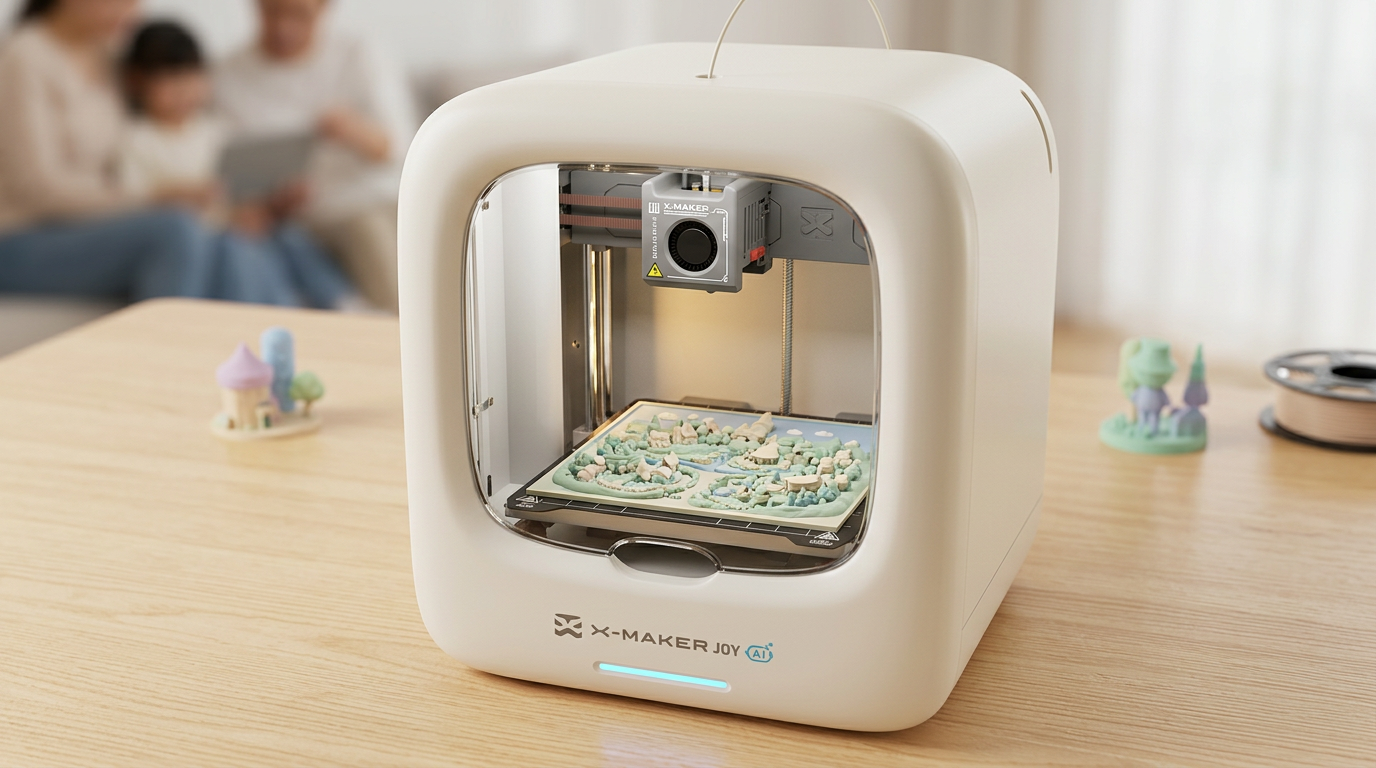
Orientation may be handled in a full desktop slicer or inside a guided app. For younger beginners, look for a workflow that previews the model's contact area and supports while still giving an adult a clear way to review or change the result.
Three current specifications matter for orientation decisions: usable build volume, supported layer-height profiles, and the printer's documented material and speed limits. Verify them on the exact product page, then use the slicer preview to confirm fit, supports, and estimated duration rather than transferring one model's limits to another printer.
For a guided family workflow, verify enclosure behavior, leveling steps, material support, build volume, preview access, and what an adult must review before printing. Do not infer these details from a product image or from the phrase kid-friendly.
For the model-library side, verify how files are reviewed, how often content changes, whether instructions and age guidance are provided, and whether a child can customize a model without losing an adult review step.
WHEN COMPARING A KID-FRIENDLY 3D PRINTER, CHECK BUILD VOLUME, MODEL PREVIEW, SUPPORT CONTROLS, AND HOW EASILY AN ADULT CAN REVIEW ORIENTATION BEFORE PRINTING.
Common beginner mistakes and the quick fix

|
What you see |
What it means |
Fix it by |
|
Corners of the base curl upward |
Warping. Too little plate contact or uneven cooling. |
Re-orient onto a wider face. Round or chamfer sharp bottom corners. |
|
Bottom layer bulges outward |
Elephant foot. Nozzle sat too close, or the bed ran hot. |
Add a small chamfer to bottom edges. Recheck levelling. |
|
Print detaches partway up |
Base footprint was too small for the height. |
Lay the model down, or split it and print in two parts. |
|
Drooping strands under a ledge or bridge |
The unsupported angle or bridge exceeds what the current printer and profile can handle. |
Rotate while checking the preview, or add supports where the test shows they are needed. |
|
Toy snaps at the same spot every time |
Layer joints sit across the load. |
Re-orient so layers run along the direction of pull. |
|
Rough patches on the visible face |
Supports were touching a display surface. |
Rotate so supports contact the back or base instead. |
|
Model is missing chunks in the app preview |
Broken or non-watertight mesh, not an orientation problem. |
Repair the mesh, or pick a reviewed model from the library. |
|
Print never starts because it will not fit |
Rotation pushed the model past the build area. |
Place it diagonally, scale down, or split it. |
When to re-orient, and when to just add supports
Re-orient the model when:
- The part will be pulled, bent, or dropped, and strength matters more than looks.
- Supports would land on a face, a logo, or a mating surface.
- The current orientation leaves an unstable footprint and a broader face, split, brim, or other tested change is available.
- A tested rotation reduces a critical overhang without creating a worse support, finish, fit, or strength problem elsewhere.
- Print time is long and a flatter position would cut layer count.
Add supports instead when:
- The model is decorative and surface scars land somewhere hidden anyway.
- Every orientation you try creates a new overhang somewhere else.
- A round horizontal hole has to stay dimensionally accurate.
- The model only fits the build volume in one position.
- Your child chose the pose and the print is about their design, not efficiency.
Conclusion
Orientation costs no filament to test in the slicer, but a poor choice can add support, reduce bed contact, damage a visible face, or weaken a loaded feature. Use five checks: footprint, load direction, overhangs, visible surfaces, and build-volume fit.
For families, these orientation rules are useful starting points, but the exact workflow and supervision requirements depend on the printer being used. If you are considering an AOSEED model, verify the exact variant’s current age and supervision guidance, operating requirements, software and model-library features, price, warranty, and return terms on AOSEED’s current regional product page, manual, and policies before buying.
FAQs
What is the best orientation for a 3D print?
There is no universal best orientation. Choose the position that balances bed contact, support use, surface finish, strength direction, build-volume fit, and removal risk for the specific model.
Should the largest flat side always face the build plate?
It is often a good starting point, but not a rule. Use another face when the flat side contains important detail, creates trapped supports, weakens the part under its expected load, or does not fit the available build area.
How does orientation affect 3D-print strength?
Material-extrusion prints are directional, so the same model can fail differently after rotation.
- Loads carried along continuous extrusion paths are often better supported.
- Loads that peel layers apart can expose weaker interfaces.
- Thin pins, hinge points, and screw features deserve their own orientation check.
How does orientation affect support material?
Rotating a model changes which surfaces begin in mid-air and which slopes exceed the printer's unsupported capability. A small tilt may reduce support, but the result depends on geometry, cooling, speed, layer height, and the selected support settings.
How should I arrange several models on the build plate?
Arrange them so each model remains inside the printable area and the printer can travel safely between them.
- Give each model enough spacing for brims, skirts, and toolhead clearance.
- Keep tall narrow parts away from crowded travel paths.
- Confirm all objects use compatible material and profile settings.
- Preview the complete plate, not only the first object.
What if no orientation avoids supports?
If every orientation leaves a critical overhang, use the least damaging option.
- Place support contact on a hidden or easy-to-finish surface.
- Use support blockers or paint-on supports when the slicer provides them.
- Split the model at a logical seam and join the parts after printing.
- Print a small test section before committing to the full model.
Sources
- National Institute of Standards and Technology, "Materials Testing Standards for Additive Manufacturing of Polymer Materials"
- Polymers (peer-reviewed, via PubMed Central), "Process Design and Parameters Interaction in Material Extrusion 3D Printing: A Review"
- CDC / National Institute for Occupational Safety and Health, "Approaches to Safe 3D Printing: A Guide for Makerspace Users, Schools, Libraries, and Small Businesses"
- Washington State Department of Health, "3D Printers"
- National Institutes of Health, NIH 3D, "Frequently Asked Questions"


Further reading

STEM Building Toys for Kids: Blocks, Kits and Printers Compared

Toy 3D Printer: What to Look for in a Printer That Makes Toys at Home

Personalized Gifts for Kids: Name Tags, Keepsakes and Custom Toys You Can Design