How to Prevent Warping in Large 3D Prints
A corner lifts. Then a second one. By hour nine the base of a 20-hour print has curled off the plate, and the nozzle is dragging a loose model around the bed.
Warping is not a mystery. Hot plastic goes down, cools, and shrinks. Every line pulls a little as it hardens. On a big footprint those small pulls add up across a long edge until they beat whatever is holding the part down. Small prints hide this. Large prints cannot.
The fix order matters more than the fix list. Changing bed temperature, adding a raft, adjusting fan speed, and swapping filament all at once makes it hard to identify the real cause. Use a one-variable-at-a-time order instead: inspect the symptom, verify the full-footprint first layer, prepare the plate, add holding area, stabilize temperature, and only then change slicer settings or model geometry.
Quick pick: match the symptom to the first thing to change
|
What you see |
Most likely cause |
First thing to change |
|
Corners lift in the first 5 to 10 layers |
Weak first-layer adhesion |
Clean the plate, then check Z-offset |
|
Print stays flat, then bends after hours |
Room or airflow changed mid-job |
Block the draft, add a draft shield |
|
Thin walls curl near the top |
Part cooling too strong for the material |
Cut fan speed, set a minimum layer time |
|
Whole model comes free of the plate |
Wrong or worn build surface |
Match surface to filament, add a brim |
|
Cracks between layers, no base lift |
Cold chamber or low nozzle heat |
Raise nozzle 5°C, close the enclosure |
|
One corner lifts, every time, same spot |
Uneven bed heating or a low spot |
Full-bed first-layer test, then relevel |
What Counts as a Large Print, and Why Size Changes Everything
Large Is Relative to Your Build Plate

There is no fixed threshold. Not in millimetres. A model counts as large when it fills most of the plate, runs many hours, or has a long flat base. On a 300 mm machine that might be a 250 mm panel. On a 150 mm machine it might be a 130 mm one. The failure mode is identical.
Footprint beats height. A tall narrow tower rarely warps at the base. A wide flat plate almost always tries to.
Why Long Edges Pull Harder Than Short Ones
Contraction scales with length. A 250 mm edge shrinks roughly ten times as far as a 25 mm edge over the same temperature drop, and the force at the corner grows with it. That is why a small test cube passes while the full model fails. Same profile. Same filament. Different distance.
Sharp corners are worse. They collect the pull from two edges at once, and they lift first, nearly every time.
Long Jobs Meet Changing Rooms
A 40-hour print sits through two nights. Things change. Heating cycles. Air conditioning. Sunlight through a window, a door left open, a fan that comes on at dusk. Any of these can cool one wall faster than the other and create uneven contraction halfway up a part that was perfectly flat at layer 40.
Large beds heat unevenly too. The sensor reads one spot. Outer corners often sit several degrees cooler than the centre. That is exactly where broad prints start to peel.
|
Before a long job: run a first-layer test that covers the same area as the real model. A centre calibration square will never find a low outer corner. |
The Physics Behind Warping, in Plain Terms
Cooling Plastic Shrinks, and Shrinking Plastic Pulls

The nozzle lays material down well above room temperature. It cools within seconds and contracts. One layer does nothing. Two hundred layers generate real internal tension, and the bottom of the part is the only anchored surface, so the stress collects where the model meets the plate.
Then the edge rises. That is the entire mechanism.
How Much Each Filament Actually Moves
Thermal movement depends on both the material and the test conditions, so datasheet coefficients should not be treated as a direct ranking of printed filaments.A study on the thermal expansion of plastics used for 3D printing tested spiral samples made from ABS, PETG, TPU, and PLA as they cooled from about 70°C to 30°C. The materials showed different amounts of contraction under those test conditions, with TPU showing the lowest heat shrinkage in the experiment.
One detail is easy to miss. Measured contraction on printed samples came out lower than datasheet figures for every material tested. A printed part is not solid stock. Infill, walls and internal voids all change how the material behaves.
|
Filament |
Warping risk |
Typical bed |
Best use on a large print |
|
PLA |
Low |
50 to 60°C |
Display models, cosplay parts, school projects, anything decorative |
|
PETG |
Low to moderate |
70 to 85°C |
Brackets, covers, containers, indoor parts that take knocks |
|
ABS |
High |
90 to 110°C |
Heat-resistant housings, parts you plan to smooth |
|
ASA |
High |
90 to 110°C |
Outdoor covers and anything facing sunlight |
|
Nylon / PC |
Very high |
90 to 110°C+ |
Tough functional parts, enclosed machines only |
Treat spool numbers as a starting point. Two spools both labelled PLA can want different bed settings. Pigment alone shifts it.
Where the Stress Collects
Four places, in rough order of failure frequency. Base corners on a wide flat footprint. Long straight edges with nothing spreading the load. Points where a narrow section suddenly widens. Thin overhangs near the top.
Match the fix to the location. Corner lift at the start is an adhesion problem. Cracks at layer 300 are a heat problem. Confuse the two and you lose a day.
Diagnose First, Then Change One Setting
Corners Lifting in the First Ten Layers

Early lift is the plate. Not the profile. Fingerprint oil, a Z-offset set too high, a first layer printed too fast, a bed running cool, or the part fan spinning up before the base has bonded.
Look at the lines. A good first layer looks slightly squashed, with each line touching the one beside it and no gaps or raised ridges. Round, separate lines mean the nozzle sits too high. Extra bed heat will not fix that.
Warping That Starts Hours Into the Job
Something changed. Either the room or the geometry.
Check the room first, because it costs nothing. An open door. An air conditioner cycling on. Late-afternoon sun crossing the bench. Then open the slicer preview at the exact height where the model bent. A section that suddenly widens puts a large mass of contracting plastic above a narrower base, and that pulls hard.
Curling at the Top and Cracks Between Layers
These look similar and have opposite causes. Curling on thin walls and overhangs usually means too much cooling, or layers so small the nozzle returns before the plastic has set. Cracks between layers usually mean too little heat, at the nozzle or in the air around the part.
Fix one. Check. Then fix the other. Raising nozzle temperature to cure curling makes a stringy mess and solves nothing.
|
Do not stack changes. One variable per test print, and write down what you changed. A result you cannot attribute is not a result. |
Build Plate Prep That Actually Holds
Clean the Plate Properly
Skin oils and residue can weaken first-layer adhesion. Clean the build surface using the method recommended by its manufacturer, since smooth PEI, textured sheets, coated plates, and glass may require different care. Depending on the surface, the approved method may involve mild dish soap and water or isopropyl alcohol. Let the plate cool before cleaning, and avoid unapproved solvents or abrasive cleaners.
Strip old glue when it builds up. Dried adhesive in uneven layers creates real height differences across a large first layer. Bad news on a big footprint.
Level the Bed and Set the Z-Offset

Automatic levelling measures the bed. That is all it does. It will not tighten a loose screw or flatten a bowed sheet. Run levelling once the plate is at printing temperature, since some surfaces shift slightly as they heat.
Move the Z-offset in small steps. Around 0.02 mm at a time. Closer if lines stay round and separate, further away if the nozzle scratches the surface or pushes up rough ridges. Small changes here shift adhesion across the entire footprint.
Slow and Widen the First Layer
Two settings do most of the work. Speed and width. Drop first-layer speed to somewhere around 15 to 30 mm/s so the plastic has time to press into the surface. Then widen the first-layer line to roughly 110 to 120 percent of nozzle diameter, which puts more material against the plate and against the line beside it.
Keep first-layer acceleration low too. Hard direction changes tug at corners before they have bonded. Corners are where it starts.
Brims, Rafts, and Mouse Ears

When a Brim Is Enough
Start here. A brim runs connected lines around the base and spreads holding force outward, without lifting the model onto a separate platform. Five to ten millimetres handles moderate warping. A large ABS or ASA part may want 10 to 20 mm.
Width is not everything. If the brim lines are not bonding to each other or to the plate, adding more just wastes filament. Watch the outer edge during the first few layers. Stop the job early if the brim itself starts to curl.
When a Raft Earns Its Material
Rafts cost time, filament and a rougher bottom surface. Use them sparingly. They earn it when the base has poor contact, when the plate is uneven, or when a brim has already failed twice. Set the air gap carefully. Too little fuses the raft to the model. Too much weakens the bottom layers.
Mouse Ears for Stubborn Corners
Small discs. Ten to 20 mm across, placed only at the corners that lift, one or two layers tall so they trim away cleanly. This puts holding power exactly where thermal stress collects, without a brim wrapping long straight edges that were never a problem.
|
Adhesion aid |
Holding power |
Material cost |
Reach for it when |
|
Skirt |
None |
Very low |
You only need to prime the nozzle and check flow |
|
Brim |
Moderate to high |
Low |
Broad base with sharp corners; your default first try |
|
Mouse ears |
High, but local |
Very low |
Two or three corners lift and the rest of the edge is fine |
|
Raft |
High |
High |
Small contact area, uneven plate, or a brim already failed |
|
Removal: let the print reach room temperature before lifting it. Trim brims and ears with flush cutters, working away from your hands. If removal takes heavy force, widen the brim gap slightly next time. |
Temperature, Cooling, and the Room Around the Printer
Set Bed and Nozzle Temperature to the Job
Stable heat beats maximum heat. Every time. PLA usually starts near 50 to 60°C at the bed, PETG around 70 to 85°C, ABS and ASA somewhere between 90 and 110°C. Adjust in 5°C steps. Compare grip and bottom finish after each test.
Too hot brings its own problems. Soft, swollen or glossy lower layers, and a part that fights removal. Nozzle temperature is a separate lever. It owns layer bonding, not base adhesion. Raise it 5°C at a time when layers split or lines look starved.
Preheat properly on a big plate. The sensor hits target well before the whole surface is evenly warm, and a thick aluminium or glass bed can need several extra minutes. Same corner lifting every time? Heating is uneven, not wrong.
Why an Enclosure Helps, and Where It Stops Helping

An enclosure blocks drafts and slows heat loss. Both matter. That is exactly what ABS, ASA, nylon and polycarbonate need, and it is the single most effective piece of hardware for high-shrink materials on large parts.
There are tradeoffs. PLA needs strong part cooling, and a hot chamber works against that. Electronics have limits. A closed chamber also changes how emissions behave in the room, which is why university safety guidance treats enclosures as a containment measure alongside ventilation rather than as a replacement for it.
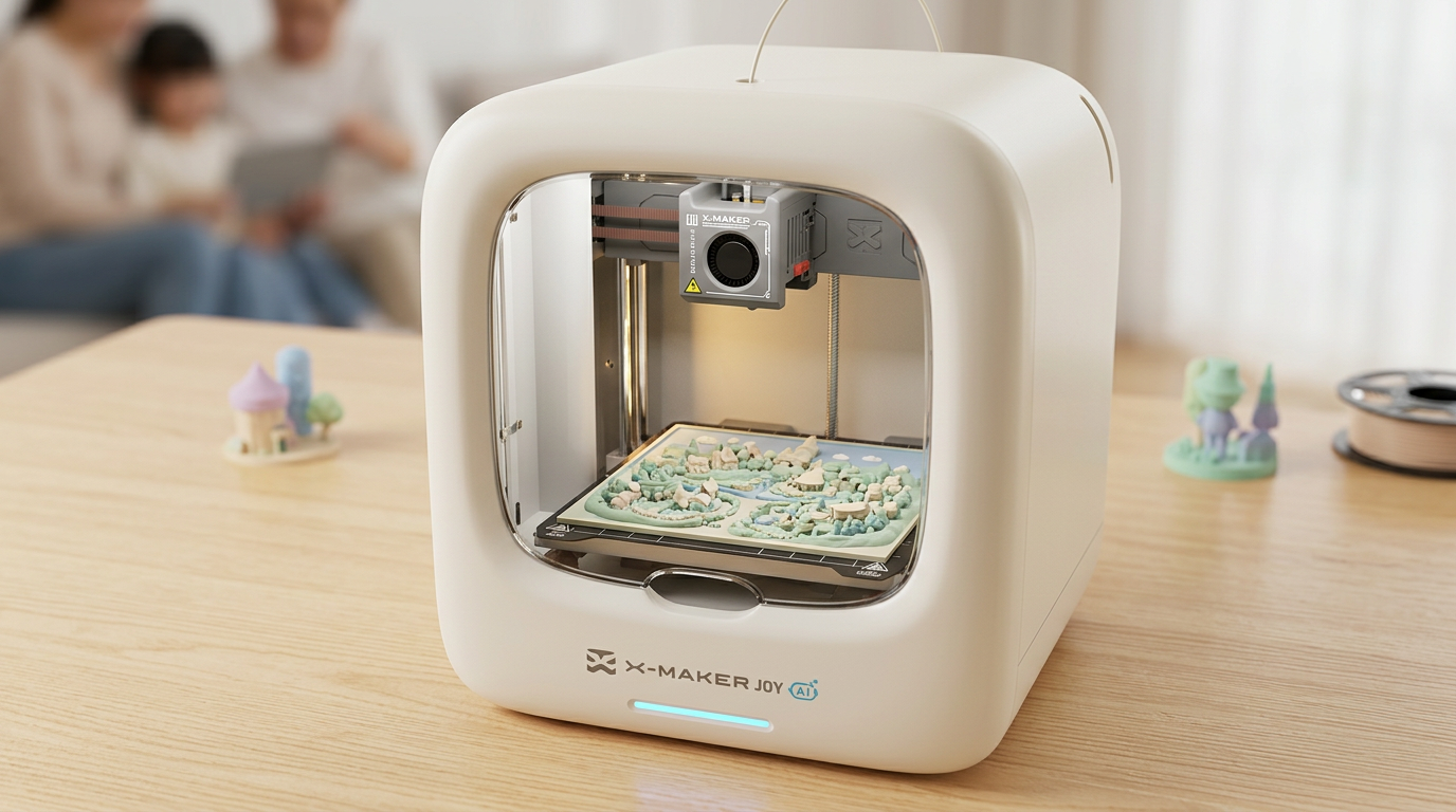
For home and classroom setups the hardware can settle this before it starts. An enclosed printer sized for family projects removes most of the draft problem outright, and the closed door doubles as a guard around hot parts. Federal guidance on safe 3D printing in schools, libraries and makerspaces pairs that containment with sensible room ventilation and a printer kept out of the space where people sit for hours.
|
Ventilation still applies. An enclosure contains heat and blocks drafts. It does not replace fresh air. Run the printer in a well-ventilated room, follow the maker’s material list, and keep heat-sensitive electronics outside any heated chamber. |
Drafts, Sunlight, and Fan Speed by Material
Turn part cooling off, or keep it low, for the first three to five layers. Sometimes ten. That is reasonable on a broad base with no early bridges. Do not confuse the part fan with the hotend fan. The hotend fan protects the heat break and should run as designed.
After that, material decides. PLA wants the most cooling. PETG prefers moderate airflow. ABS and ASA want little or none, except across bridges. Nylon and polycarbonate profiles tend to run low fan as well.
Then look at the room. Not the slicer. Move the printer away from windows, vents, ceiling fans and busy doorways, and check airflow at different times of day. A room that feels still at 8am can be moving air by 3pm.
Slicer Settings and Nozzle Choice for Big Parts
Layer Height, Wall Count, and Infill Pattern
Infill pattern deserves more attention than it gets. A finite element study of printing parameters against residual stress and warpage found that infill pattern was a significant contributor to reducing warpage across all three materials it tested. Layer thickness showed comparatively low sensitivity. Printing temperature mattered strongly for one material and barely at all for the others.
The practical reading is simple. Balanced patterns such as grid, cubic or gyroid spread support in several directions. Long straight infill lines pull harder along one axis. Density is not a cure. Dense infill just adds more hot plastic that then has to cool and contract inside the part.
Walls do it more efficiently. Add perimeters around loaded faces instead of raising infill everywhere.
Matching Nozzle Size to Layer Height
A bigger nozzle puts down wider, thicker lines. Fewer of them, too. That means less print time, more contact between neighbouring paths, and each layer holding heat a little longer before the next arrives. The tradeoff is real. Visible layer texture, and lost detail on small features.
|
Nozzle |
Layer height range |
Extrusion width |
Suits |
|
0.4 mm |
0.20 to 0.30 mm |
0.44 to 0.48 mm |
Detail, small holes, text, curved surfaces |
|
0.6 mm |
0.30 to 0.45 mm |
0.66 to 0.72 mm |
General large parts; the useful middle ground |
|
0.8 mm |
0.40 to 0.60 mm |
0.88 to 0.96 mm |
Props, fixtures, bulky structural shapes |
Use a validated layer-height range for the installed nozzle and material, following the printer manufacturer or slicer profile as the starting point. If you move outside that range or change nozzle size, check extrusion consistency and recalibrate flow before printing.
Staying Inside the Hotend Flow Limit
Volumetric flow is the real ceiling, not millimetres per second. Layer height times line width times speed gives cubic millimetres per second, and a hotend can only melt so many. Push past it and quality collapses. Thin lines, extruder clicking, weak layers, surface gaps. Measurement work on polymer extrusion and melt rheology at NIST covers why melt behaviour, rather than motor speed, sets that upper bound.
Run a flow test on the filament and hotend you actually own. Then set maximum volumetric speed below the point where quality starts to break down. Slow the machine instead. That is safer than pushing temperature past the material range.
Design Choices That Lower the Force

Put the Largest Stable Face Down
More contact resists more pull. Choose the flattest, broadest face the design allows, then watch how cross-section changes as layers rise. A model that widens sharply above a narrow base builds strong pulling forces near that transition.
Rotate the part and compare four things before committing. Support volume. Print time. Seam position. Bed contact. The orientation that looks natural on screen is often not the one that prints flat.
Round the Corners and Avoid Long Thin Bases
A sharp corner concentrates force from two long edges into one point. A fillet spreads it along a curve. Even a small radius helps. Brim removal gets cleaner too.
Long narrow strips are the other classic trap. They shrink along their length and bow, even when the first layer looked perfect. Widen the base where the design allows. Add temporary corner tabs. Keep transitions between thick and thin sections gradual.
Split Oversized Models Into Sections
Cutting a model reduces footprint, shortens each job, and lowers the amount of filament at risk in a single failure. Each piece also gets its own best orientation.
Place seams where they can be hidden or sanded. Then plan the joints. Add alignment pins, dovetails or keyed joints, and allow for printer tolerance, since a perfect fit in CAD is usually too tight after extrusion. For a smaller build volume this is not a compromise. It is how large projects normally get made.
|
BUILT FOR STEADY CHAMBERS, NOT DRAFTY BENCHES. MOST WARPING ADVICE ASSUMES AN OPEN-FRAME MACHINE ON A COLD TABLE. AOSEED TAKES THE OTHER ROUTE. THE KID-FRIENDLY PRINTERS THAT PRINT INSIDE A CLOSED CHAMBER SHIP FULLY ENCLOSED, PRE-ASSEMBLED AND AUTO-LEVELLING, SO THE THREE THINGS THAT WRECK LARGE PRINTS, DRAFTS, A CROOKED FIRST LAYER AND A COLD ROOM, ARE HANDLED BEFORE A CHILD EVER OPENS THE APP. |
When to Adjust Settings and When to Change the Setup
Keep Tuning Your Current Profile When
- The first layer looks uneven in one area but fine everywhere else. That is a levelling job, not a hardware job.
- Only sharp corners lift while the long edges stay down. Mouse ears solve this for pennies.
- You are printing PLA or PETG in a stable room. Both forgive a lot once the plate is clean and the Z-offset is right.
- Cracks appear between layers with no base lift. Nozzle temperature and fan speed cover most of these.
- The failure moved after your last change. Movement means you found a real variable, so keep going.
Change the Setup or the Model When
- Every corner lifts on every material after a clean plate, a fresh level and a brim. The room is the problem.
- You need ABS, ASA, nylon or polycarbonate on a broad part and have no enclosure. Draft shields help, but they are not equivalent.
- The model is longer than it is wide and has a thin base. No profile change beats splitting it or adding tabs.
- The same corner fails repeatedly on a large bed. Uneven heating will not be fixed in the slicer.
- Print time has crossed 30 hours on a machine you cannot supervise. Smaller sections lose far less when something goes wrong.
Nine-Step Troubleshooting Order
Work Top to Bottom, One Change at a Time
- Note exactly where the warping starts: base, middle, top, or between layers. Photograph it before removing the model.
- Inspect the first layer across the full footprint the model uses, not just the centre.
- Wash and relevel the plate at printing temperature. Check for loose screws and debris under the sheet.
- Correct the Z-offset in 0.02 mm steps before touching any temperature.
- Set bed temperature to the filament maker range and preheat for several extra minutes.
- Add a brim, or mouse ears if only specific corners lift.
- Delay part cooling for the first layers and block drafts at the printer, not in the slicer.
- Review speed, wall count and infill pattern. Lower excessive density before adding anything.
- Reorient, fillet the base corners, or split the model. Reprint a small section of the hardest area first.
|
Save the profile. Name it with the material, nozzle size and build surface once a large print succeeds. The next one then starts from a known-good baseline instead of memory. |
Conclusion
Flat large prints come from four unglamorous things. None of them are settings tweaks. A clean plate. A correct Z-offset. A stable bed temperature. A slow, wide first layer. Brims, mouse ears and rafts add holding power on top of that foundation, but none of them rescue a first layer that never bonded.
Material and design carry the rest. PLA and PETG stay flat far more easily than ABS, ASA or nylon on a wide footprint. Rounded corners, a broad contact face, moderate infill and gradual changes in cross-section all lower the pulling force before the print even starts.
When something fails, find where the damage began before rewriting the profile. Corner lift at the start points at adhesion. Cracks at hour twelve point at drafts, cold air or weak layer bonding. Test one correction. Record it. Keep the settings that worked.
Hardware can remove several setup variables, but printer specifications still need to match the project. As checked on August 13, 2026,AOSEED lists the Single X-MAKER AI+ at $339 in its U.S. store for ages 9–16, with a 150 × 150 × 150 mm build volume and support for PLA and ABS. Its heated bed is rated up to 110°C; when printing ABS, follow the filament and printer guidance for ventilation and use adult supervision, especially during early sessions. Smaller build volumes are not a limit on big projects because larger models can be split into sections and assembled after printing. A family setup built for repeatable results matters more in month six than in week one.
FAQs
Is PLA or PETG more prone to warping?
PETG, slightly. Not by much. Both sit far below ABS, ASA, nylon and polycarbonate on warping risk, so the gap between them is small next to the gap to any high-shrink material. PLA cools and hardens quickly, which helps it hold shape on an open-frame machine in an ordinary room. PETG stays soft longer. It can pull at corners when the plate is dirty, the fan runs too hard, or the model has a long sharp-edged base. Published contraction measurements support this, with PET-type material showing the strongest shrinkage on cooling among common filaments tested. Formula matters too, so a modified PLA blend may not behave like basic PLA. Practical tip: choose PLA for the easiest large decorative print, and PETG when the finished part needs toughness or moisture resistance.
How do you stop large PETG prints from warping?
Clean plate, correct Z-offset, heated bed, low early cooling, brim on the long edges. That order solves most of it. In that sequence. PETG warps less than engineering filaments, but a large footprint still generates enough contraction to lift a weak area. Start from the filament maker range, which usually puts the bed warmer than PLA. Resist pushing higher. An over-hot bed leaves the lower layers soft and can bond PETG hard enough to damage smooth PEI or glass during removal. Keep the part fan off or low for the first several layers, then raise it only as far as bridges and overhangs actually need. Check the first layer across the whole footprint, since large models reach cooler or poorly levelled areas a small calibration square never touches. Practical tip: add 10 to 20 mm mouse ears to the lifting corners before committing to a full raft.
Can the wrong bed temperature warp PLA prints?
Yes. In both directions. A bed running cool will not hold the first layer against the pull from everything above it. A bed running hot leaves the base soft and swollen, which lets the model shift and makes removal ugly. Bed temperature is only one part of the first-layer system though, and it is not the part that fails most often. A dirty surface, a Z-offset set too high, a fast first layer or a cold draft will all cause lifting while the temperature reading looks perfectly correct. Raising bed heat cannot compensate for a nozzle sitting too far above the plate, or for lines that never touched each other. Different PLA blends want different settings, so use the spool maker range rather than a number copied from another printer. Practical tip: change the bed by about 5°C per test and hold every other setting still.
What is the most common cause of warping?
Uneven thermal contraction, always. Plastic goes down hot, cools, shrinks, and the resulting stress pulls corners and edges away from the plate. On a desktop machine, though, the condition that lets contraction become visible warping is usually weak first-layer adhesion. Oil on the plate, an incorrect Z-offset, poor levelling, low bed heat or early fan cooling all leave the base unable to resist that pull. Large and long parts make it far more obvious, because stress accumulates across a greater distance. Where the failure appears narrows it down fast. Corners lifting in the first minutes point at adhesion, while warping or cracks developing hours in point at drafts, chamber temperature, geometry or layer bonding. Practical tip: clean the plate and run a full-footprint first-layer test before changing a single slicer value.
At what temperature does PLA warp?
There is no single number. None. Behaviour depends on the blend, part shape, internal stress, load, orientation, and how evenly the model cooled while printing. Standard PLA has limited heat resistance compared with PETG and ABS, and published heat-deflection figures for it typically sit well below those materials. Those are test-condition values though, not a guaranteed failure point for a finished object. A thin PLA panel under load can deform at a lower temperature than a thick unloaded block of the same material. Dark parts left in direct sunlight or inside a parked car heat unevenly and can develop soft areas and permanent bends. Annealed and heat-resistant PLA blends behave differently again. Practical tip: do not use ordinary PLA for a load-bearing part that will sit near engines, heaters, sunlit windows or in an enclosed vehicle.
How do you reinforce large 3D prints?
Walls, ribs, gussets and local thickness beat dense infill almost every time. Those features put material where the part actually carries load, without adding print time, heat and contraction everywhere else. Extra infill does add stiffness. It also packs more hot plastic inside the model, and that plastic has to cool and shrink too, which raises internal stress on a broad part. Several perimeters plus targeted reinforcement usually outperform 80 or 100 percent infill across a whole object. Keep transitions between thick and thin areas rounded so force spreads instead of concentrating, and keep reinforcement balanced across the shape, since a very thick section beside a thin panel cools at a different rate and bends. Practical tip: add ribs and extra walls around screw holes, joints and loaded faces, and leave decorative areas at moderate infill.
What is the 45 degree rule in 3D printing?
It is an overhang guideline. Not a warping rule. A surface rising at roughly 45 degrees or more from horizontal usually gives each new layer enough material underneath to hold the next line without support. Treat it as a rough default. Nozzle size, layer height, cooling, speed, filament and line width all shift where the real threshold sits. Slicers expose the overhang angle as an adjustable value precisely because different machines and materials handle different slopes, and a well-tuned PLA profile often prints steeper overhangs than a warm PETG or ABS one. The rule also has nothing to do with bed warping. Sloping a wall to 45 degrees may cut support use, but it will not correct a dirty plate or uneven bed heat. Practical tip: print an overhang test in your final filament and layer height before removing supports from a large model.
How do you 3D print something that is too big?
Split it. Splitting is the usual answer, and it brings real advantages beyond simply fitting the plate. Shorter individual jobs. Less filament at risk in one failure. Freedom to orient each piece for its own best combination of strength and bed contact. Cut along natural lines where the seam can be hidden or sanded, then add alignment pins, dovetails, screws or keyed joints so assembly is repeatable. Allow clearance for printer tolerance, because a joint that fits perfectly in CAD is usually too tight once extrusion width is accounted for. Rotating a model diagonally across the plate sometimes buys enough room for a borderline case. Practical tip: print one test joint before committing to the full set of sections, and check the fit at the layer height you plan to use.
Sources
- National Library of Medicine, “Thermal Expansion of Plastics Used for 3D Printing”
- National Library of Medicine, “Material-Dependent Effect of Common Printing Parameters on Residual Stress and Warpage Deformation in 3D Printing”
- NIOSH, Centers for Disease Control and Prevention, “Approaches to Safe 3D Printing: A Guide for Makerspace Users, Schools, Libraries, and Small Businesses”
- National Institute of Standards and Technology, “Polymer Advanced Manufacturing and Rheology”
- The Ohio State University Environmental Health and Safety, “3D Printer Safety”









Further reading

Thanksgiving STEM Activities for Kids: Table Projects and Simple Engineering Challenges

Halloween STEM Activities for Kids: Spooky Builds That Teach Real Science

STEM Crafts for Kids: Build, Decorate and Test