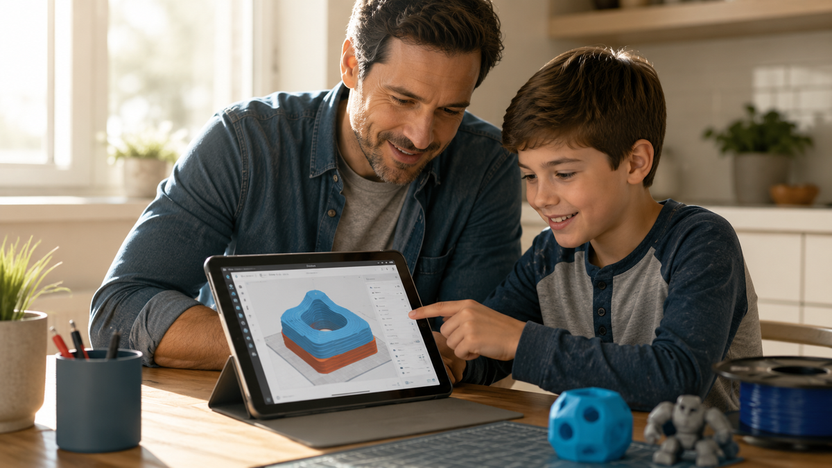
What Is a Slicer in 3D Printing? 9 Settings Parents Need to Know

A 3D-printing slicer converts a digital model plus the selected printer and material profile into layer-by-layer toolpaths and a printer-ready file. Without that step, a raw model does not tell the machine where to move, when to extrude, or which temperatures and speeds to use.
Parents do not need to tune every control. Start with a manufacturer-tested profile, then understand the nine settings that most directly affect detail, structure, supports, adhesion, material flow, duration, and cooling.
Before exporting, open the layer preview and check model fit, first-layer contact, supports, walls, infill, estimated time, and filament. Safe operation still depends on the exact printer manual, approved material, responsible-adult supervision, placement, ventilation or other exposure controls, and restricted access to hot and moving parts.
The 9 Settings at a Glance
|
Setting |
What It Changes |
Where to Start |
|
Layer height |
Surface smoothness and total print time |
Leave the standard profile alone |
|
Infill density |
How solid the inside is, plus filament used |
Low for toys and display pieces |
|
Wall count |
Shell thickness and real-world durability |
Raise this before raising infill |
|
Supports |
Whether overhangs print or sag |
Let the slicer generate them, then look |
|
Print speed |
Job length and how hard the motion system works |
Tested profile only, no manual bump |
|
Nozzle temperature |
Whether filament flows and bonds |
Match the filament, then stop |
|
Bed temperature |
First-layer grip on the plate |
Match the filament and surface |
|
Build plate adhesion |
Skirt, brim, or raft under the model |
Lightest option that actually works |
|
Cooling fan speed |
How fast fresh plastic hardens |
Use the material preset |
What Is a Slicer in 3D Printing?
A slicer converts a digital model and the selected printer/material settings into layer-by-layer toolpaths. The original file may remain unchanged, but orientation, scale, mesh repair, compensation, and printable-resolution limits can change the resulting toolpath and effective printed geometry.
The description holds up at industrial scale too. NIST describes additive manufacturing as fabricating parts directly from an electronic file that is virtually sliced into many thin layers, then built up in sequence into a finished part. A desktop printer in a kitchen and a metal system in a factory both depend on that same slicing step.
How the Slicer Connects the Model to the Printer
A basic mesh such as STL mainly describes surface geometry. Richer formats such as 3MF can also preserve units, materials, components, metadata, and manufacturing information, but the slicer still needs a correct printer and material profile to create executable toolpaths.
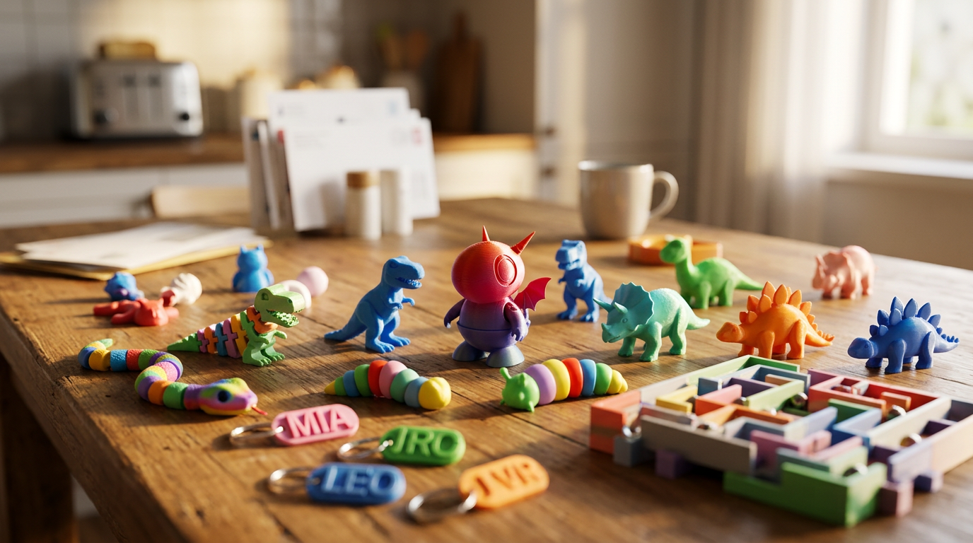
Picture that downloaded dinosaur. The file knows the shape of the tail. It has no opinion on where the nozzle should start, how thick each layer should be, whether the front legs need something underneath them, or how hot the plastic should get. The slicer answers every one of those questions before printing begins.
Shape in. Manufacturing plan out.
What Goes In, and What Comes Out
STL, OBJ, and 3MF are common inputs in consumer filament workflows, but support varies by slicer. Confirm the exact software’s supported formats; 3MF can preserve richer project and manufacturing data, while STL mainly carries triangulated surface geometry and may not preserve units.
3MF is the newest of the three and was built to hold richer manufacturing data than raw geometry. It has since become an international standard: the 3MF Consortium publishes the specification suite as ISO/IEC 25422:2025, and one of its published extensions covers 2D sliced model data inside the package itself.
The output differs from the input. Many filament printers receive G-code, while others use a machine-specific package. The output contains printer instructions; the input may contain only geometry or may preserve richer project data, depending on the format.
|
TIPCheck the file type before choosing a model. If the slicer cannot open it, select a supported export or return to the original design file. Keep the editable source when a model was made in CAD, because revising the source is usually more reliable than repairing an exported mesh. |
How Slicing Works, Step by Step

The workflow is short. Six steps. A beginner can follow all of them on a first print.
- Import the model onto the virtual build plate and confirm it fits inside the printable area.
- Select the printer profile and the filament. This is the step that carries build dimensions, nozzle setup, and machine behaviour.
- Position and orient the object. Which face touches the plate changes supports, strength, surface finish, and time.
- Choose or accept the print settings. A tested profile handles most of this automatically.
- Press slice. The software divides the model into horizontal sections and calculates every toolpath.
- Open the preview, scroll through the layers, then export the printer-ready file.
The preview is the final checkpoint before export. Use it to confirm first-layer contact, supports, walls, infill, fit within the build area, and the estimated time and filament.
The 9 Slicer Settings Parents Need to Know
Start from a tested printer and material profile. Use the nine settings below to understand why a print came out the way it did, not as a checklist to change before the first attempt.
1. Layer Height
Layer height sets the thickness of each horizontal slice. Thinner layers mean more of them, which shows up as smoother curves and a longer job. A rounded helmet benefits visibly. A rectangular box does not.
2. Infill Density
A display figure rarely needs a solid core, but it may need enough internal support for top surfaces and handling. Start with the validated profile, inspect the sliced preview and estimated grams, and adjust only for the model’s geometry and use.
3. Wall Count
Walls, sometimes called perimeters, form the outer shell. Adding walls thickens that shell and may strengthen a shell-dominated part more efficiently than raising infill, but the result depends on geometry, load, material, orientation, and print quality. Test the critical feature.
4. Supports
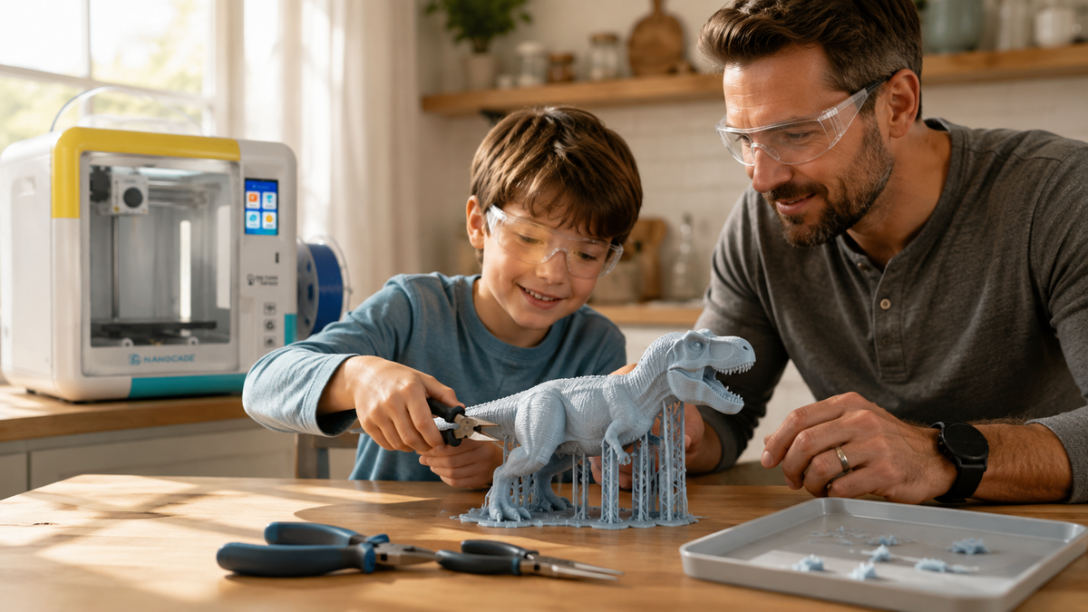
A printer can bridge some gaps and build some overhangs without support, but the reliable limit depends on geometry, cooling, speed, layer height, material, and profile. The slicer adds temporary support where the selected rules require it, and that support must be removed after printing.
Rotating the model often beats increasing support density. Try the rotation first.
5. Print Speed
Speed controls how fast the toolhead completes its paths. A slicer normally runs different speeds for outer walls, infill, first layers, and travel moves. One number rarely describes the whole job. Let the machine prove itself before you push it.
6. Nozzle Temperature
The nozzle has to melt filament enough for steady extrusion and layer bonding. Too cold, and layers separate. Too hot brings its own defects.
Temperature is not only a quality setting. Washington State Department of Health guidance for schools tells staff to select the lowest temperature appropriate to the filament in use, specifically to limit unwanted emissions. The same logic applies on a kitchen counter. Match the preset. Then leave it alone.
7. Bed Temperature
Bed temperature matters at the foundation. Enough heat helps the first layer stay put while the rest of the model builds on top.
Some PLA profiles can print without a heated bed, which removes that specific heated-surface exposure. The nozzle and hot end, freshly extruded plastic, and moving parts still require restricted access, responsible adult supervision, and the controls specified in the current manual.
8. Build Plate Adhesion
Three options show up here. They are not interchangeable. A skirt prints around the model without touching it, which primes the nozzle and gives an early read on flow. A brim attaches to the first layer and widens the footprint. A raft builds a whole platform underneath.
Use the least intrusive adhesion aid that solves the observed problem. Start from the tested profile and first-layer setup; a raft on a broad stable base may add unnecessary material and cleanup.
9. Cooling Fan Speed
Cooling decides how quickly fresh plastic sets. The right behaviour changes with the material and the stage of the print, which is why profiles often reduce cooling on early layers and raise it later. Maximum fan is not the answer.
|
WORTH KNOWING Two of these nine settings touch home safety, not just print quality. The nozzle block and heated bed reach temperatures that burn on contact, and Princeton University’s environmental health and safety office notes that the heat needed to melt feedstock is itself a fire risk during a malfunction. Its guidance prefers fully enclosed printers with interlocked guards, and it recommends waiting after a job finishes so the machine cools and contaminants disperse before the lid opens. On emissions, NIOSH published a 40-page guide for makerspaces, schools, and libraries after evaluating printer and filament combinations for ultrafine particles and chemical exposure. Ventilate the room. Keep the printer away from where children sit for long stretches. Do not hover over a running machine. |
Layer Height, Infill, and Print Time

Layer height, infill, and walls can create large trade-offs among finish, structure, material, and duration. Read the slicer estimate for the actual model before committing to a long print.
|
Choice |
What You Gain |
What It Costs |
Sensible For |
|
Fine layers |
Smoother curves, sharper small detail |
Noticeably longer job for the same height |
Miniatures, rounded shapes, gifts |
|
Standard layers |
Balanced finish and time |
Nothing much, which is why it is the default |
Toys, organisers, school models |
|
Thick layers |
Fast result |
Visible stepping on curves |
Fit tests and quick prototypes |
|
Low infill |
Less filament, shorter job |
Softer interior under load |
Display pieces, decorations |
|
High infill |
Denser core |
More plastic and a lot more time |
Only when the part carries real force |
|
Extra walls |
Real strength gain per gram |
Small time and material increase |
Brackets, hooks, usable parts |
Read the estimate after every meaningful change. If a small model suddenly takes much longer or uses substantially more filament, compare the setting changes and preview before exporting.
What G-Code Actually Tells the Printer

G-code is the command language many filament printers use. Most beginners will not write it directly because the slicer generates it, but a short preview helps explain what the printer has been instructed to do.
The table below shows common Marlin-style examples, not commands guaranteed for every printer or firmware. The slicer normally generates them automatically; beginners should verify the exact machine documentation rather than editing G-code by hand.
|
Command |
What It Does |
Which Slicer Setting Produced It |
|
G0 / G1 |
Move in a straight line, with or without extruding |
Speed, layer height, toolpath calculation |
|
M104 / M109 |
Set the hotend temperature, or set it and wait |
Nozzle temperature |
|
M140 / M190 |
Set the bed temperature, or set it and wait |
Bed temperature |
|
M106 / M107 |
Set fan speed, or turn the fan off |
Cooling fan speed |
|
M221 |
Set the flow percentage applied to extrusion moves |
Flow-percentage override applied to extrusion moves; firmware-specific |
One file. Thousands of these lines. The slicer wrote all of them from the choices made on screen.
|
GUIDED WORKFLOW OR SETTINGS PANEL?A beginner may benefit from tested presets and fewer visible choices. A more advanced learner may benefit from a layer preview and documented controls. The right balance depends on who will diagnose failed prints and how much an adult will supervise. |
How Much Slicer Control Does Your Child Actually Need?
This is the question the nine settings are really for. Some children want to tune. Others want a finished dinosaur. Both are fine. Ask the child. The answer depends on them, not the machine.
When comparing printer workflows, check the current product page, manual, and app or software documentation for the exact model and region. Confirm which controls are available, which presets are manufacturer-approved, and what age and supervision guidance applies; recheck these details before publication because software, bundles, and product terms can change.
|
Workflow feature |
Preset-led printer |
Advanced-control printer |
|
Typical fit |
Younger beginners who want quick starts |
Older learners who want to diagnose and tune |
|
Settings access |
Tested profiles with fewer visible controls |
Layer height, walls, supports, speed, temperature, and cooling |
|
Preview |
May be simplified or hidden; verify before buying |
Layer preview helps diagnose supports, time, and toolpaths |
|
What to verify |
Offline printing, profile updates, and parent controls |
Compatible slicer, correct printer profile, and export options |
When Presets Are Enough
- Presets may be enough when the learner wants a guided model-to-print workflow and is not yet interested in changing settings. Follow the exact printer’s verified age and responsible-adult supervision guidance regardless of software complexity.
- The main use is the model library and light customisation.
- You would rather not be asked about infill percentages on a school night.
- The supported material and tested PLA profiles cover the projects you actually plan to make.
When You Want Real Slicer Control
- Your child already asks why a print failed instead of just being annoyed.
- School or club projects need parts that fit together and hold up.
- You want a preview screen so problems get caught before filament is spent.
- A second material and a larger build area would actually get used.
Slicer Mistakes That Waste Filament
Before changing hardware, check these five common profile and preview errors. If the same failure persists across known-good files and approved profiles—or involves heat, electrical, motion, or sensor faults—stop the printer and follow the manual or contact support.
- Wrong printer profile. Build dimensions and machine settings come from this choice. Two similar printers in one list is all it takes.
- Infill raised without a defined need. A decorative toy at high density may add print time and material without correcting weak geometry, poor layer bonding, or the wrong orientation.
- Missing supports. The solid model view looks fine. The sliced view is where you find the arm starting in mid-air.
- Speed increased beyond the printer and material profile. A slower completed print is more useful than a faster setting that creates repeated failures; change speed only within documented limits and evaluate one change at a time.
- Six settings changed at once. If the next print is different, you will not know which change did it. Move one thing, slice, compare.
That last one is the most useful habit a child can pick up here. Change one variable. Observe. Adjust.
A Preview Check Before You Press Print

The preview shows the toolpaths the printer has been instructed to follow, which can differ from the unsliced model view. The five checks below can reveal common problems before filament is used.
- Orientation. Is the model resting on a sensible face rather than balanced on a point?
- First layer. Drag the slider to the bottom and see how much of the model touches the plate.
- Supports. Find where they begin. Confirm the important overhangs got some.
- Walls and infill. Move to the middle of the model. The interior should look the way you intended.
- Estimate. Compare time and filament against what the object is worth to you.
|
TIPReview the preview with the child when appropriate. It is a practical way to connect orientation, supports, walls, infill, time, and filament use with the toolpaths the printer will follow. |
Conclusion
A slicer is the translator between a shape and a machine. It cuts the model into layers, plans every path, applies the printer and material settings, and writes the file the printer executes. Nothing more.
You do not need to master it. Start from a tested profile, learn what layer height, infill, walls, supports, speed, the two temperatures, adhesion, and cooling each do, and open the preview before every job. Match the filament temperature rather than raising it, because that setting affects the air in the room as well as the finish on the print.
If you are choosing hardware, compare printers by profile quality, preview access, export options, supported materials, and how much control the learner can use under responsible adult supervision. Before buying, verify the exact model and region on the manufacturer’s current product page, manual, and software documentation for age guidance, supervision requirements, current price, warranty, returns, and supported features.
FAQs
What does a 3D-printing slicer do?
A slicer turns a 3D model into printer-specific layers and toolpaths. It applies the printer profile, material, orientation, walls, infill, supports, temperatures, speeds, and cooling settings, then produces the file the printer can run.
Can you 3D print without using a slicer?
Only when someone else has already sliced the model for the exact printer and material, or when slicing is built into a guided app or cloud workflow. A raw STL, OBJ, or 3MF model still needs to be converted into printer instructions somewhere.
Can I use any slicer with any 3D printer?
Not automatically. Compatibility depends on whether the slicer has a correct printer profile and can export a format the machine accepts.
- Build volume and origin must match the printer.
- Nozzle, start and end routines, and firmware commands must be correct.
- The material profile must stay within the printer's supported temperatures.
Which slicer settings should a beginner change first?
Start with a tested preset and change only settings that answer a clear project need.
- Layer height for detail versus time
- Walls and infill for structure
- Supports and build-plate adhesion for geometry
- Temperature only when the filament or manufacturer profile requires it
How accurate are slicer time and filament estimates?
They are planning estimates, not guarantees. Accuracy improves with a correct printer profile, acceleration limits, filament diameter, and start/end routines; actual time can still change because of firmware behavior, heating, calibration, or pauses.
What should I check in the preview before printing?
Use the layer preview as the final checkpoint.
- Confirm the model is inside the build area and has a stable first layer.
- Inspect overhangs, bridges, and where supports begin.
- Check walls, infill, and top surfaces at several heights.
- Review the estimated time and filament before exporting.
Sources
- National Institute of Standards and Technology, “Measurement Science for Additive Manufacturing Program”
- National Institute for Occupational Safety and Health, “Approaches to Safe 3D Printing: A Guide for Makerspace Users, Schools, Libraries, and Small Businesses”
- Washington State Department of Health, “3D Printers”
- Princeton University Office of Environmental Health and Safety, “3D Printers on Campus”
- 3MF Consortium, “3MF Specifications”
- Marlin Firmware, “G-code Index”


Further reading

STEM Building Toys for Kids: Blocks, Kits and Printers Compared

Toy 3D Printer: What to Look for in a Printer That Makes Toys at Home

Personalized Gifts for Kids: Name Tags, Keepsakes and Custom Toys You Can Design